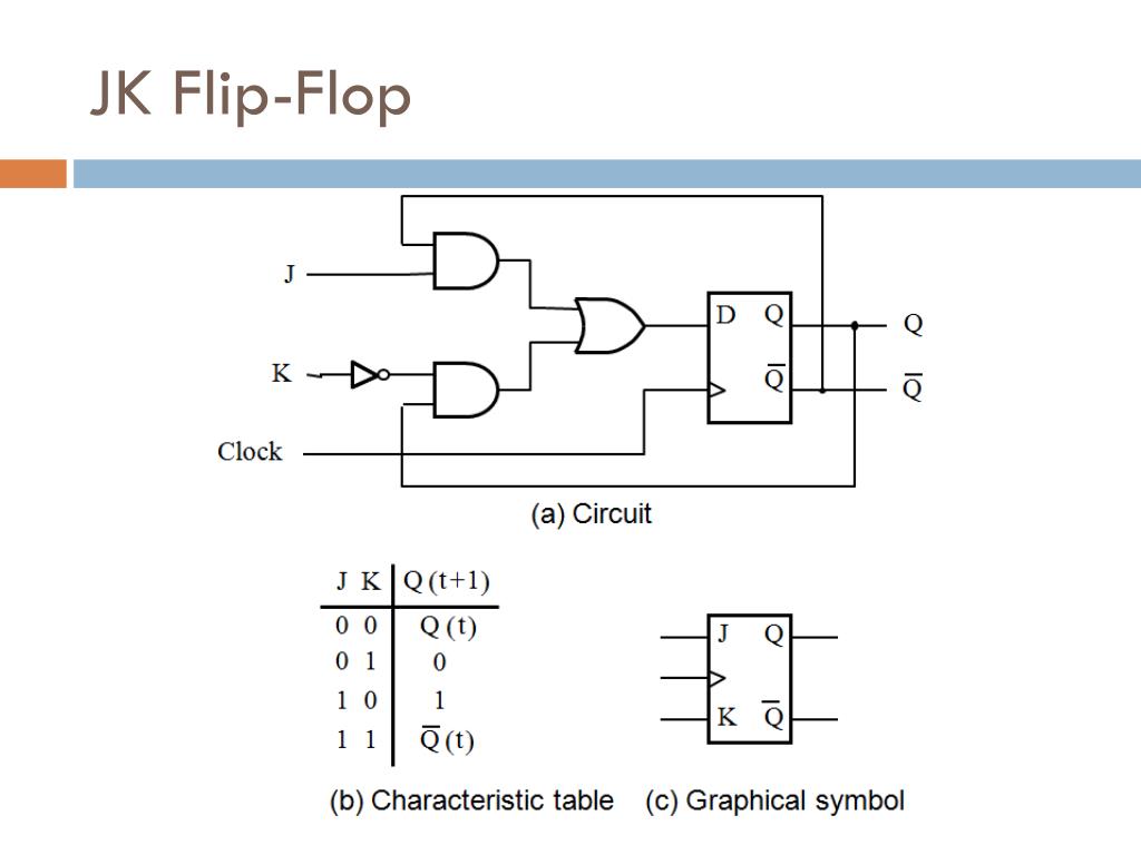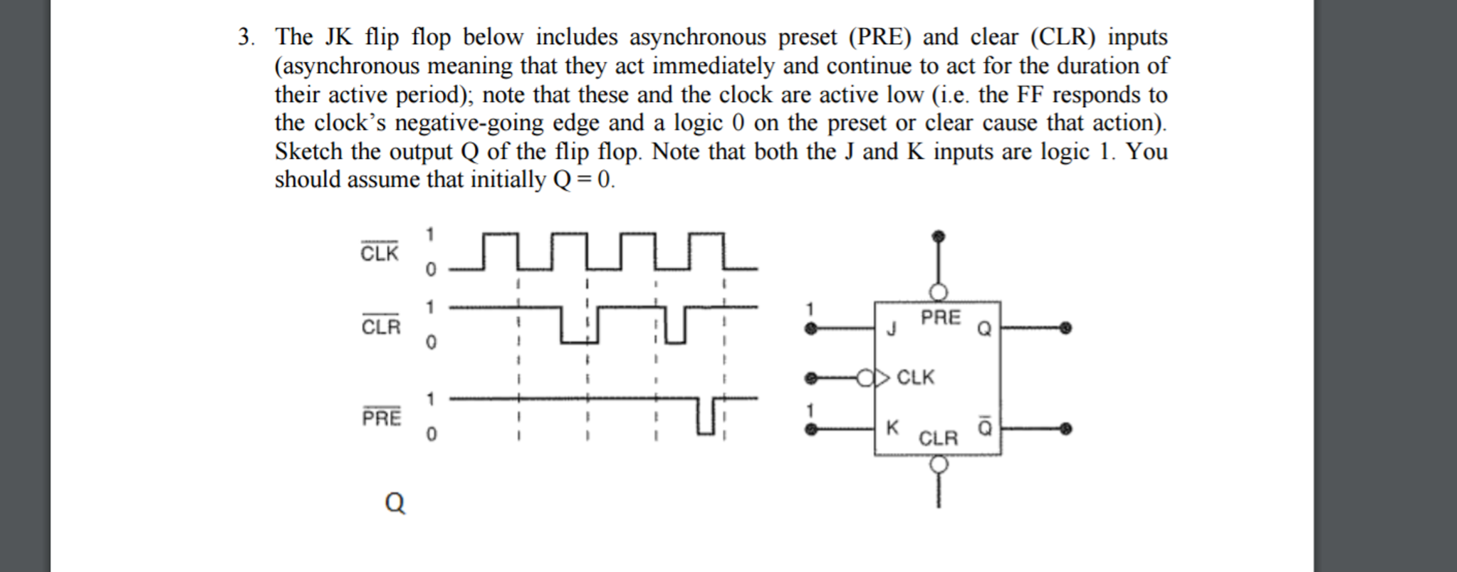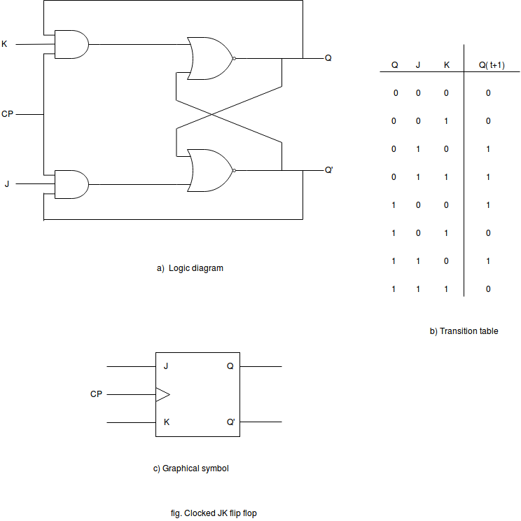
The disadvantage here is that we need two separate inputs, D and Clk to make it toggle. That is the D-type flip-flop configuration only allows the output at Q to have the same steady state condition as the D input when clocked HIGH. Thus the steady state condition of its output only toggles HIGH or LOW each time its clock input is pulsed, if and only if there is a change to the data input (D). Then we can define the switching action of the D-type flip-flop in Boolean form as being:

Where Q is the present state and Q+1 is the next state after the application of a single clock pulse. Conversion of JK Flip-flop into D-type Flip-flop The D-type flip-flop can also be used to provide temporary storage of one bit of information the same as the toggle flip-flop.

The D-type flip-flop has two inputs, D (Data) and CLK (Clock) and changes state in response to a positive or negative edge transition on the clock input. Conversion of JK Flip-flop into D-type Flip-flopĪs well as bistable JK flip-flop’s, we can also produce a toggling action using D-type or Delay flip-flop’s constructed from a simple modification of a clocked JK circuit. Then we can represent the switching action of a toggle flip-flop using a 2-input Exclusive-OR (Ex-OR) gate. This idea of Q+1 is HIGH only when either of the inputs is HIGH but not when both inputs are HIGH, that is either input but not both represents the same Boolean Algebra expression of an Exclusive-OR Function which is given as: You may have noticed that the characteristic equation given in Boolean form for the toggle flip-flop above will produce an output HIGH for the next state ( Q+1) if the two inputs of T and Q are different, and a LOW output if these inputs are the same. Where: Q represents the present steady state of the flip-flop and Q+1 is the next switching state. Then we can define the switching action of the toggle flip-flop in Boolean form as being: Characteristics Table for the Toggle Function CLK Thus the Q output of the flip-flop “toggles” at each positive going edge (for this example) of the CLK pulse. The negative transistion of the CLK pulse at time t 4 from HIGH to LOW once again has no effect on the output. The negative transistion of the clock pulse from HIGH to LOW at time t 2 has no effect on the output at Q as the flip-flop is reset into one stable state.Īt the next rising edge of the clock signal at time t 3, the logic “1” at T passes to Q, changing its state making output Q HIGH again. At the rising edge (assuming positive transistion) of a CLK pulse at time t 1, the output at Q changes state and becomes LOW, making Q HIGH. Now let’s suppose that input T is HIGH (T = 1) and CLK is LOW (CLK = 0). Thus the output remains unchanged when T = 0. At the rising edge or falling edge of a CLK pulse, the logic “0” condition present at T prevents the output at Q from changing state. Suppose that initially CLK and input T are both LOW (CLK = T = 0), and that output Q is HIGH (Q = 1). Hopefully we remember from the previous tutorial that the JK flip-flop is classed as an Asynchronous flip-flop where its input condition (HIGH or LOW), and its present steady state condition, both determine its next switching state. Toggle flip-flops, TFF’s or simply “T-type flip-flops” are not available commercially as a dedicated TTL or CMOS logic chip, they can be easily constructed by connecting together the J and K inputs of a basic JK flip-flop where the J input behaves like a Set (S) command, and the K input behaves like a Reset (R) command.

Toggle flip-flops have a single input and one or two complementary outputs of Q and Q which change state on the positive edge (rising edge) or negative edge (falling edge) of an input clock signal or pulse. Toggle flip-flops can be used as a basic digital element for storing one bit of information, as a divide-by-two divider or as a counter. The Toggle Flip-flop is another type of bistable sequential logic circuit based around the previous clocked JK flip-flop circuit.


 0 kommentar(er)
